In 2025, with increasingly stringent discharge standards (e.g., China Class 1A, EU Water Framework Directive updates, and US EPA nutrient limits), the MBBR (Moving Bed Biofilm Reactor) process remains one of the most efficient and widely adopted biological wastewater treatment technologies worldwide. This article provides a detailed typical MBBR process flow diagram, step-by-step explanation, key components, and real-world applications to help engineers, plant operators, and consultants design or upgrade systems effectively.
Whether you’re handling municipal sewage, industrial wastewater (food & beverage, petrochemical, textile), or aiming for water reuse/ZLD, understanding the MBBR process flow is essential for achieving >90% COD/BOD removal, >95% ammonia nitrification, and >75% total nitrogen reduction in a compact footprint.
Why MBBR Process Flow Stands Out in Modern Wastewater Treatment
- No sludge recirculation needed (unlike traditional activated sludge)
- 30-50% smaller footprint than CAS/MBR
- Superior shock load resistance (hydraulic & organic fluctuations)
- Lower sludge production (0.25-0.4 kg TSS/kg BOD vs. 0.5-0.7 in CAS)
- Easy integration with IFAS, MBR, or tertiary processes for nutrient recovery
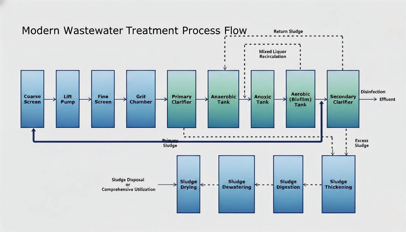
Typical MBBR Process Flow Diagram (2025 Standard Configuration)
Below is a complete, sequential MBBR wastewater treatment process flow commonly used in plants from 1,000 m³/day to 100,000+ m³/day. Many systems now incorporate pre-anoxic/anaerobic zones for enhanced nutrient removal (BNR).
- Influent / Coarse Screen Removes large solids (plastics, rags, branches) to protect downstream pumps and equipment.
- Pumping Station / Lift Pumps Elevates wastewater for gravity flow through the plant.
- Fine Screen Captures smaller debris (hair, fibers, particles >3-6mm).
- Grit Chamber / Vortex Grit Removal Settles sand, gravel, and heavy inorganics to prevent abrasion on aerators and media.
- Primary Sedimentation Tank (Optional) Gravity removal of settleable solids and 30-40% BOD (often skipped in pure MBBR for compact designs).
- Anaerobic/Anoxic Tank (Pre-Denitrification, Optional but Common in 2025) Hydrolysis of organics + phosphorus release; prepares carbon source for denitrification.
- Anoxic Tank Denitrification: Nitrate (NO₃⁻) → Nitrogen gas (N₂) using influent carbon.
- Aerobic MBBR Tank (Core Biofilm Reactor) Plastic biofilm carriers (500-900 m²/m³ protected surface area) suspended in aerated wastewater. Simultaneous BOD/COD removal + nitrification (NH₄⁺ → NO₃⁻).
- Mixed Liquor Recirculation (Nitrate Recycle) 200-400% recirculation from aerobic to anoxic zone for total nitrogen removal.
- Secondary Clarifier / DAF / Lamella Settler Separates sloughed biofilm and suspended solids. (Many 2025 plants use DAF or media filtration for better solids capture.)
- Disinfection (UV/Chlorine/Ozone) Pathogen inactivation for safe discharge or reuse.
- Effluent Discharge or Tertiary Treatment Advanced filtration/polishing for water reuse.
Sludge Handling Process in MBBR Systems
MBBR produces significantly less excess sludge than traditional processes:
- Primary Sludge (if primary settler used)
- Excess Biological Sludge from secondary separation
- Sludge Thickening (gravity or mechanical)
- Anaerobic/Aerobic Digestion (volume reduction + biogas production)
- Dewatering (centrifuge/belt press, 20-30% DS)
- Drying/Incineration/Land Application or resource recovery (fertilizer, building materials)
Key Advantages of This MBBR Process Flow (2025 Perspective)
- High Efficiency: Biomass concentration 8-15 g/L on carriers → faster reaction rates
- Modular & Scalable: Add media volume for capacity increase without new tanks
- Resilient Operation: Biofilm withstands toxic shocks, pH/temperature variations
- Energy Efficient: Optimized aeration (SOTE >10%) + no RAS pumps
- Future-Proof: Easily upgraded to MBBR-IFAS or MBBR-MBR for zero liquid discharge
Real Project Examples Using This Flow
- 50,000 m³/day Municipal Plant (China, 2024 upgrade): Pre-anoxic + 3-stage aerobic MBBR → TN <10 mg/L, footprint reduced 45%
- Food Processing Wastewater (Europe): High-strength influent → Anaerobic pre-treatment + MBBR → COD <100 mg/L, biogas recovery
- Industrial Park Retrofit (India): Existing tanks converted to MBBR → Capacity doubled without land expansion
This MBBR process flow diagram represents the gold standard for cost-effective, high-performance wastewater treatment in 2025. If you’re designing a new plant or upgrading an old one, this configuration consistently delivers compliance while minimizing OPEX.
Need a customized P&ID, media selection advice, or process calculation for your specific influent? Contact our engineering team for a free consultation and quotation.
#MBBR #WastewaterTreatment #MBBRProcessFlow #BiofilmReactor #WaterReuse #EnvironmentalEngineering #SewageTreatmentPlant